DRSSTC 2.0
Producing sparks...
This Tesla coil is the largest we’ve built so far, and it’s possibly the biggest one in Spain. It’s capable of generating electric arcs several meters long, and with the right setup, it can modulate musical tones and even play songs.
The entire project was built from scratch, using IGBT transistors to switch at the resonant frequency and enable such high-voltage discharges. A special power supply configuration was also used to make it compatible with a household electrical system.

Specifications
– Nominal power: 12 kW
– Full-bridge IGBT: SKM400
– MMC: 10 kV, 0.66 µF
– Resonant frequency: 37 kHz
– Secondary coil: 2164 turns
– Filtering: 700 V, 6800 µF
– Snubber: 1200 V, 4 µF
– Maximum current (limited): 1000 A
– Maximum bus voltage: 650 V
– ZCS control using primary current feedback
Primary design
The primary circuit consists of a copper coil with 10 turns, but in this case, it’s tapped at the 7th turn to operate at the resonant frequency. The MMC capacitor, on the other hand, is made up of 220 capacitors rated at 1000 V and 330 nF, resulting in a 10 kV, 660 nF capacitor that stores enough energy to power the resonant circuit effectively.
Both the primary coil and the capacitor are connected to the power circuit using two parallel 35 mm² cables to reduce the resistance of the RLC circuit and allow for higher currents.For the safety of the system and the power electronics inside the coil, a strike rail was installed above the primary circuit to prevent arc discharges. This strike rail is directly connected to ground.


Secondary design
The secondary circuit is made with 2164 turns of 0.7 mm² copper wire, protected by five layers of insulating varnish, similar to the 3 MOT Tesla Coil project. The coil is wound around a 200 mm diameter tube, giving the secondary a 4:1 aspect ratio and an inductance of 258 mH.
The capacitive part of the secondary consists of the coil’s internal capacitance combined with the capacitance of the toroid. It was designed for a target frequency of 40 kHz, since the resonance frequency will slightly decrease during operation due to the effect of electrical discharge. The toroid is made of hollow aluminum, with a minor diameter of 30 cm and a major diameter of 115 cm.


Full bridge and DC bus
This is the heart of the DRSSTC—the part that switches the entire resonant circuit for long enough to allow energy transfer from the primary to the secondary. It consists of four SKM400 transistors, capable of switching up to 400 A under nominal conditions. These transistors are mounted on a large aluminum heatsink to prevent overheating during extended use and to avoid failures.
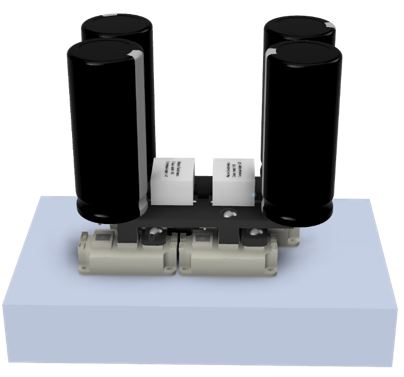
On the other hand, the entire power circuit operates on direct current. Since the power supply is AC, input filter capacitors are required to provide the current demanded by the RLC circuit during charging. The capacitors used are rated at 350 V and 6800 µF; with four arranged in a series-parallel configuration, the resulting setup is 700 V and 6800 µF. These components are housed in a very compact layout using copper busbars to minimize inductance and resistance in the power stage.


Current Transformers
To ensure the system switches at the resonant frequency, it’s essential to have feedback from the current in the primary circuit. The key to double-resonant Tesla coils is that the transistors switch at the exact resonant frequency, allowing the system to operate under Zero Current Switching (ZCS) conditions, which greatly improves switching performance.
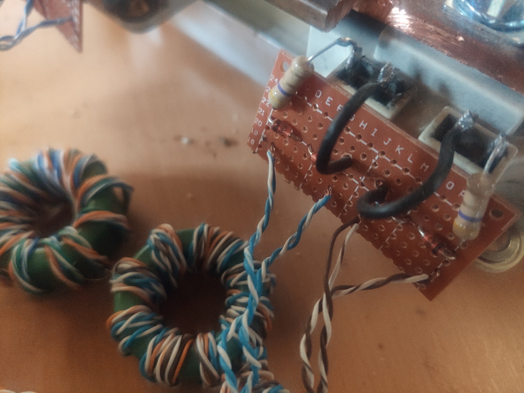
To obtain current feedback, two current transformers are used in cascade with a 1:32–1:32 ratio, resulting in a total transformation ratio of 1:1024. The core is specially rated to avoid saturation at high frequencies.
An identical pair of transformers is used for overcurrent detection in the primary circuit, enabling current limiting via the control system.
For the gate drivers, a similar core is used, but in this case, the GDTs (Gate Drive Transformers) are designed to provide isolation and a bipolar signal for faster transistor switching. Their winding ratio is 1:1:1 with 10 turns to prevent saturation. Each GDT is connected to the gate of two IGBTs in such a way that when one turns on, the other turns off. The GDTs output a 24 V bipolar waveform.

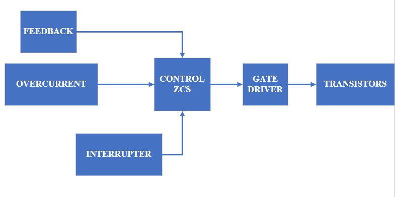
Control system
The control system is the brain of the Tesla coil. It’s responsible for receiving the primary current feedback, filtering it, and switching the system at its resonant frequency. This driver operates under ZCS conditions at 37 kHz. To make the system resonate at this frequency, it uses the primary current as a reference. From this signal, two square waveforms at 37 kHz, in phase with the primary current, are generated. These signals are sent to a driver consisting of two MOSFETs powered at 24 V, which feed the GDTs for the IGBTs, delivering sufficient gate current for proper switching.
Since the Tesla coil handles extremely high currents—up to 1000 A—the system does not operate at a 100% duty cycle. Instead, it’s controlled by a switch connected via fiber optic to the control circuit. This switch sends activation signals to the control unit at specific moments. This feature allows the DRSSTC to be modulated with pulses at desired frequencies.

Power Supply
The system’s power supply converts the AC mains voltage into DC. In Spain, the mains supply is 220 V RMS, which corresponds to 315 V peak. This power supply uses a simple voltage doubler made with two diodes and two capacitors, delivering 630 V peak in DC. By increasing the bus voltage, the maximum current in the primary circuit also increases.
A variac (variable transformer) is used to gradually power the circuit and control the voltage, since directly applying full voltage would cause a large inrush current that could trigger protection systems due to capacitor charging

Test and Results
In this project, all currents and voltages in the system were thoroughly analyzed to ensure proper operation. In an initial test, the system’s resonance was verified and checked for stability under a current of 100 A. For measurement, a resistor was connected to the overcurrent transformer, and signals were observed using an oscilloscope.
The duty cycle was controlled using the interrupter. At duty cycles below 10%, the resonant coupling and energy transfer between the primary and secondary functioned correctly. However, at higher duty cycles, the energy transfer between circuits led to a reverse energy flow from the secondary back to the primary, reducing the system’s efficiency.
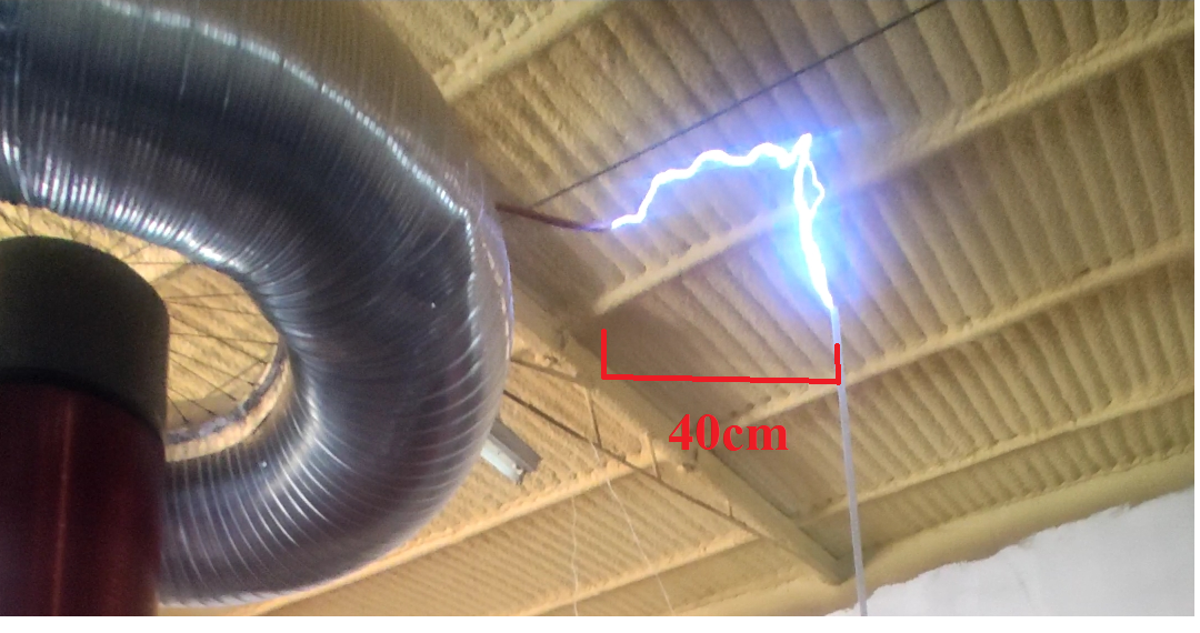
Extensive testing was carried out, and once optimal performance was achieved, discharges of up to 2.8 meters were generated with very high brightness. It’s important to note that the primary circuit current is limited to 1000 A for safety.
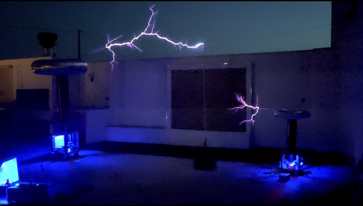
Multiple Tesla coils were also tested together, jointly controlled through two fiber optic links, allowing synchronized operation and even the modulation of signals to produce music.