Gas turbine
Gas turbine from junk
A jet engine turbine may seem like an extremely complex system, but its working principle is actually quite simple. It consists of a compressor-turbine assembly and a combustion chamber. The compressor draws in and compresses a large volume of air, increasing its pressure. This high-pressure air then enters the combustion chamber, where fuel is injected and ignited. The resulting expansion of hot gases flows through the turbine, generating thrust.
In this project, a jet engine turbine was built for static testing. Components were added progressively to study performance improvements and evaluate the combustion efficiency of various gaseous and liquid fuels.


Specifications
– Radial Geometry
– 80.000 rpm
– 10 kg of static thrust
– Fuels: diesel, gasoline, metane and propane
– Automatic control
– Electric generation (future)
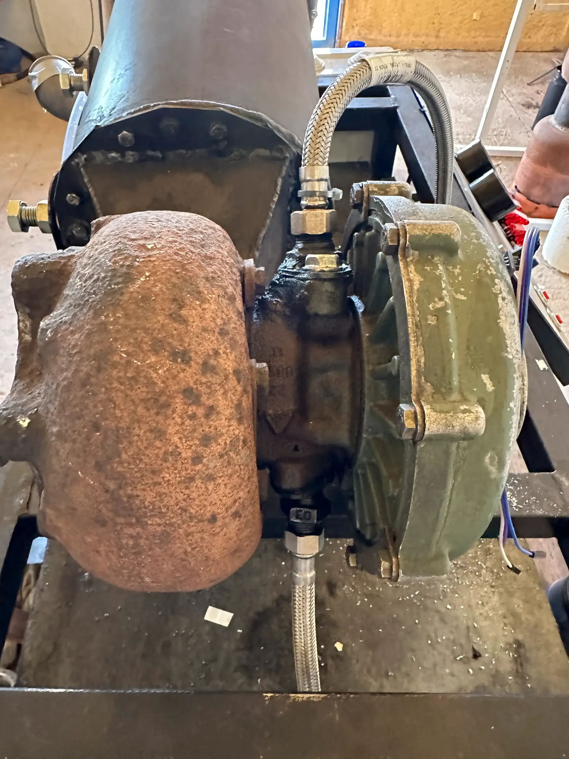
Turbocharger and combustion chamber
Due to the high cost of components used in gas turbines and aircraft engines, the most practical approach for this experimental setup is to use a car turbocharger. Unlike axial-flow turbines typically found in aircraft or combined-cycle gas turbines, automotive turbochargers feature a radial geometry, which simplifies construction and integration. In this case, to achieve greater thrust and efficiency, a Renault truck turbocharger was selected. It features a 70 mm air intake and an 80 mm turbine outlet, and is designed to operate at extremely high rotational speeds with an oil-based lubrication system.
To streamline the assembly, galvanized steel tubing was used to connect the compressor outlet. For optimal performance and temperature control, the turbine inlet is connected directly to the combustion chamber outlet, minimizing energy losses. The combustion chamber is constructed from 4 mm thick steel tubing with a 200 mm diameter, designed to safely withstand internal pressure. The side panels are sealed using 2 mm steel plates, fastened with M6 bolts. For improved flow dynamics, the exhaust path transitions into a conical shape, guiding gases smoothly into the turbine’s scroll housing.


Combustor liner
One of the greatest challenges in this project is stabilizing the flame within the combustion chamber to prevent it from moving toward the turbine section, which would result in performance loss and potential damage to the system. Various flame stabilization techniques exist, such as swirl burners, but in this case, a simplified approach was chosen using a combustor liner designed to supply air to the combustion chamber in three distinct zones.
In the primary combustion zone, 20% of the total air is introduced. The secondary combustion zone receives 30% of the air, while the remaining 50% is directed to the dilution zone. This staged airflow allows the liner to stabilize the flame and maintain combustion strictly within the chamber. The liner was fabricated using high-temperature vitrified steel tubing. By design, the outer walls of the liner are cooled by the airflow, improving thermal resistance and structural integrity during operation.


Fuel injection and evaporator
The most complex aspect of the project is enabling the turbine to burn different types of fuels. Gaseous fuels are the easiest to ignite and keep stable within the combustion chamber. For gas injection, a 5 mm copper tube is used, inserted directly into the combustion chamber at a height of 5 cm so that the gas enters the primary zone. The challenge lies in injecting liquid fuels. In industrial gas turbines, fuel is injected at very high pressure—typically around 100 bar—along with an atomizer and a swirl mechanism to produce fine droplets that mix efficiently with the air, promoting complete combustion. However, due to the high cost of high-pressure pumps and the difficulty of building a swirl burner, a simpler method was chosen.
In this project, a vaporizer system was developed using three side tubes and one central tube, into which the fuel is injected at a pressure of 2 bar. The central tube follows a reverse path, entering the secondary combustion zone and then returning to the primary zone. This ensures that the fuel, before injection, passes through high-temperature tubes, vaporizes, and then enters the primary combustion zone in a gaseous state. This vaporizer needs to reach a certain temperature to begin vaporizing the fuel. Therefore, the turbine must initially be started with gas fuel and later switched to liquid fuel operation once the system reaches the required temperature.


Oil system
Lubricating both the compressor and the turbine requires a continuous supply of oil. To achieve this, a pump capable of delivering up to 6 bar of pressure was installed. The oil is circulated through a network of metal tubing to prevent damage from high temperatures and ensure safe operation.
A similar setup is used for delivering liquid fuel to the combustion chamber. However, in this case, the injection pressure is lower, with the system operating at up to 2 bar, which is sufficient for the vaporization process used in this project.
Electronics and sensors
The turbine is monitored through a series of sensors controlled by an Arduino Mega. Two K-type thermocouples rated for up to 1000°C are used, with built-in signal conditioning, to measure temperatures at the combustion chamber inlet and the turbine outlet. For pressure monitoring, a 4–20 MPa pressure transducer is employed. Turbine rotational speed is measured using an FC-51 infrared sensor with a reflective target mounted on the compressor shaft. Sensor data is read via the Arduino’s analog inputs and transmitted to a computer through the serial port for real-time monitoring and data logging.
Pump control is handled by several PWM regulators rated at 15A and up to 36V. This allows precise control of fuel flow and oil pressure within the turbine system. All electronic components are housed in an isolated enclosure for safety and protection. The turbine also requires an ignition system to initiate combustion within the chamber. For this, a standard automotive spark plug is connected to a high-voltage generator built using a flyback transformer and a ZVS (Zero Voltage Switching) driver. Two of these igniters were built to allow for the future addition of an afterburner stage downstream of the turbine.

SCADA
The system is controlled through both a physical control panel and a computer interface. The control panel includes switches and key-operated power controls, as well as potentiometers for adjusting pump speeds and analog pressure gauges for real-time pressure readings.
The computer communicates bidirectionally with the Arduino via a serial port. A custom Python script is used to read all sensor data and display it graphically in real time. Additionally, the script includes virtual sliders that allow the user to control the pumps from the computer interface in case the physical regulators fail or are unavailable.

First fire
The first test was conducted with only the combustion chamber, without the turbine or compressor, to verify the stability of the flame within the chamber. An EDF motor was used to supply air to the chamber, simulating the role of the compressor.
The startup process was quite complex, as several factors needed to be regulated simultaneously, such as gas flow and air intake. However, after overcoming these challenges, the system successfully started and maintained stable operation for several minutes.
In subsequent tests, a small afterburner was added without fuel injection, which improved the compression within the chamber. Finally, to maximize thrust, an afterburner with fuel injection was incorporated, using diesel fuel in this case.
